Tag Archives: microservices

Introduction to Apache Flink

Apache Flink is a robust, open-source data processing framework that handles large-scale data streams and batch-processing tasks. One of the critical features of Flink is its architecture, which allows it to manage both batch and stream processing in a single system.

Consider a retail company that wishes to analyse sales data in real-time. They can use Flink’s stream processing capabilities to process sales data as it comes in and batch processing capabilities to analyse historical data.

The JobManager is the central component of Flink’s architecture, and it is in charge of coordinating the execution of Flink jobs.

For example, if a large amount of data is submitted to Flink, the JobManager will divide it into smaller tasks and assign them to TaskManagers.

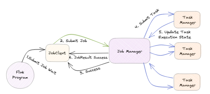
TaskManagers are responsible for executing the assigned tasks, and they can run on one or more nodes in a cluster. The TaskManagers are connected to the JobManager via a high-speed network, allowing them to exchange data and task information.

For example, when a TaskManager completes a task, it will send the results to the JobManager, who will then assign the next task.

Flink also has a distributed data storage system called the Distributed Data Management (DDM) system. It allows for storing and managing large data sets in a distributed manner across all the nodes in a cluster.

For example, imagine a company that wants to store and process petabytes of data, they can use Flink’s DDM system to store the data across multiple nodes, and process it in parallel.

Flink also has a built-in fault-tolerance mechanism, allowing it to recover automatically from failures. This is achieved by maintaining a consistent state across all the nodes in the cluster, which allows the system to recover from a failure by replaying the state from a consistent checkpoint.

For example, if a node goes down, Flink can automatically recover the data and continue processing without any interruption.

In addition, Flink also has a feature called “savepoints”, which allows users to take a snapshot of the state of a job at a particular point in time and later use this snapshot to restore the job to the same state.

For example, imagine a company is performing an update to their data processing pipeline and wants to test the new pipeline with the same data. They can use a savepoint to take a snapshot of the state of the job before making the update and then use that snapshot to restore the job to the same state for testing.

Flink also supports a wide range of data sources and sinks, including Kafka, Kinesis, and RabbitMQ, which allows it to integrate with other systems in a big data ecosystem easily.

For example, a company can use Flink to process streaming data from a Kafka topic and then sink the processed data into a data lake for further analysis.

The critical feature of Flink is that it handles batch and stream processing in a single system. To support this, Flink provides two main APIs: the Dataset API and the DataStream API.

The Dataset API is a high-level API for Flink that allows for batch processing of data. It uses a type-safe, object-oriented programming model and offers a variety of operations such as filtering, mapping, and reducing, as well as support for SQL-like queries. This API is handy for dealing with a large amount of data and is well suited for use cases such as analyzing historical sales data of a retail company.

On the other hand, the DataStream API is a low-level API for Flink that allows for real-time data stream processing. It uses a functional programming model and offers a variety of operations such as filtering, mapping, and reducing, as well as support for windowing and event time processing. This API is particularly useful for dealing with real-time data and is well-suited for use cases such as real-time monitoring and analysis of sensor data.

In conclusion, Apache Flink’s architecture is designed to handle large-scale data streams and batch-processing tasks in a single system. It provides a distributed data storage system, built-in fault tolerance and savepoints, and support for a wide range of data sources and sinks, making it an attractive choice for big data processing. With its powerful and flexible architecture, Flink can be used in various use cases, from real-time data processing to batch data processing, and can be easily integrated with other systems in a big data ecosystem.

Microservices Architectures: The SAGA Pattern

The Saga pattern is an architectural pattern utilized for managing distributed transactions in microservices architectures. It ensures data consistency across multiple services without relying on distributed transactions, which can be complex and inefficient in a microservices environment.

Key Concepts of the Saga Pattern

In the Saga pattern, a business process is broken down into a series of local transactions. Each local transaction updates the database and publishes an event or message to trigger the next transaction in the sequence. This approach helps maintain data consistency across services by ensuring that each step is completed before moving to the next one.

Types of Saga Patterns

There are several variations of the Saga pattern, each suited to different scenarios:

Choreography-based Saga: Each service listens for events and decides whether to proceed with the next step based on the events it receives. This decentralized approach is useful for loosely coupled services.

Orchestration-based Saga: A central coordinator, known as the orchestrator, manages the sequence of actions. This approach provides a higher level of control and is beneficial when precise coordination is required.

State-based Saga: Uses a shared state or state machine to track the progress of a transaction. Microservices update this state as they execute their actions, guiding subsequent steps.

Reverse Choreography Saga: An extension of the Choreography-based Saga where services explicitly communicate about how to compensate for failed actions.

Event-based Saga: Microservices react to events generated by changes in the system, performing necessary actions or compensations asynchronously.

Challenges Addressed by the Saga Pattern

The Saga pattern solves the problem of maintaining data consistency across multiple microservices in distributed transactions. It addresses several key challenges that arise in microservices architectures:

Distributed Transactions: In a microservices environment, a single business transaction often spans multiple services, each with its own database. Traditional ACID transactions don’t work well in this distributed context.

Data Consistency: Ensuring data consistency across different services and their databases is challenging when you can’t use a single, atomic transaction.

Scalability and Performance: Two-phase commit (2PC) protocols, which are often used for distributed transactions, can lead to performance issues and reduced scalability in microservices architectures.

Solutions Provided by the Saga Pattern

The Saga pattern solves these problems by:

  • Breaking down distributed transactions into a sequence of local transactions, each handled by a single service.
  • Using compensating transactions to undo changes if a step in the sequence fails, ensuring eventual consistency.
  • Flexibility in transaction management, allowing services to be added, modified, or removed without significantly impacting the overall transactional flow.
  • Better scalability by allowing each service to manage its own local transaction independently.
  • Improving fault tolerance by providing mechanisms to handle and recover from failures in the transaction sequence.
  • Visibility into the transaction process, which aids in debugging, auditing, and compliance.

Implementation Approaches

Choreography-Based Sagas

  • Decentralized Control: Each service involved in the saga listens for events and reacts to them independently, without a central controller.
  • Event-Driven Communication: Services communicate by publishing and subscribing to events.
  • Autonomy and Flexibility: Services can be added, removed, or modified without significantly impacting the overall system.
  • Scalability: Choreography can handle complex and frequent interactions more flexibly, making it suitable for highly scalable systems.

Orchestration-Based Sagas

  • Centralized Control: A central orchestrator manages the sequence of transactions, directing each service on what to do and when.
  • Command-Driven Communication: The orchestrator sends commands to services to perform specific actions.
  • Visibility and Control: The orchestrator has a global view of the saga, making it easier to manage and troubleshoot.

Choosing Between Choreography and Orchestration

When to Use Choreography

  • When you want to avoid creating a single point of failure.
  • When services need to be highly autonomous and independent.
  • When adding or removing services without disrupting the overall flow is a priority.

When to Use Orchestration

  • When you need to guarantee a specific order of execution.
  • When centralized control and visibility are crucial for managing complex workflows.
  • When you need to manage the lifecycle of microservices execution centrally.

Hybrid Approach

In some cases, a combination of both approaches can be beneficial. Choreography can be used for parts of the saga that require high flexibility and autonomy, while orchestration can manage parts that need strict control and coordination.

Challenges and Considerations

  • Complexity: Implementing SAGA can be more complex than traditional transactions.
  • Lack of Isolation: Intermediate states are visible, which can lead to consistency issues.
  • Error Handling: Designing and implementing compensating transactions can be tricky.
  • Testing: Thorough testing of all possible scenarios is crucial but can be challenging.

The Saga pattern is powerful for managing distributed transactions in microservices architectures, offering a balance between consistency, scalability, and resilience. By carefully selecting the appropriate implementation approach, organizations can effectively address the challenges of distributed transactions and maintain data consistency across their services.

Stackademic 🎓

Thank you for reading until the end. Before you go:

Bulkhead Architecture Pattern: Data Security & Governance

Today during an Azure learning session focused on data security and governance, our instructor had to leave unexpectedly due to a personal emergency. Reflecting on the discussion and drawing from my background in fintech and solution architecture, I believe it would be beneficial to explore an architecture pattern relevant to our conversation: the Bulkhead Architecture Pattern.

Inspired by ship design, the Bulkhead architecture pattern divides the base of a ship into partitions called bulkheads. This ensures that if there’s a leak in one section, it doesn’t sink the entire ship; only the affected partition fills with water. Translating this principle to software architecture, the pattern focuses on fault isolation by decomposing a monolithic architecture into a microservices architecture.

Use Case: Bank Reconciliation Reporting

Consider a scenario involving trade data across various regions such as APAC, EMEA, LATAM, and NAM. Given the regulatory challenges related to cross-country data movement, ensuring proper data governance when consolidating data in a data warehouse environment becomes crucial. Specifically, it is essential to manage the challenge of ensuring that data from India cannot be accessed from the NAM region and vice versa. Additionally, restricting data movement at the data centre level is critical.

Microservices Isolation

  • Microservices A, B, C: Each microservice is deployed in its own Azure Kubernetes Service (AKS) cluster or Azure App Service.
  • Independent Databases: Each microservice uses a separate database instance, such as Azure SQL Database or Cosmos DB, to avoid single points of failure.

Network Isolation

  • Virtual Networks (VNets): Each microservice is deployed in its own VNet. Use Network Security Groups (NSGs) to control inbound and outbound traffic.
  • Private Endpoints: Secure access to Azure services (e.g., storage accounts, databases) using private endpoints.

Load Balancing and Traffic Management

  • Azure Front Door: Provides global load balancing and application acceleration for microservices.
  • Application Gateway: Offers application-level routing and web application firewall (WAF) capabilities.
  • Traffic Manager: A DNS-based traffic load balancer for distributing traffic across multiple regions.

Service Communication

  • Service Bus: Use Azure Service Bus for decoupled communication between microservices.
  • Event Grid: Event-driven architecture for handling events across microservices.

Fault Isolation and Circuit Breakers

  • Polly: Implement circuit breakers and retries within microservices to handle transient faults.
  • Azure Functions: Use serverless functions for non-critical, independently scalable tasks.

Data Partitioning and Isolation

  • Sharding: Partition data across multiple databases to improve performance and fault tolerance.
  • Data Sync: Use Azure Data Sync to replicate data across regions for redundancy.

Monitoring and Logging

  • Azure Monitor: Centralized monitoring for performance and availability metrics.
  • Application Insights: Deep application performance monitoring and diagnostics.
  • Log Analytics: Aggregated logging and querying for troubleshooting and analysis.

Advanced Threat Protection

  • Azure Defender for Storage: Enable Azure Defender for Storage to detect unusual and potentially harmful attempts to access or exploit storage accounts.

Key Points

  • Isolation: Each microservice and its database are isolated in separate clusters and databases.
  • Network Security: VNets and private endpoints ensure secure communication.
  • Resilience: Circuit breakers and retries handle transient faults.
  • Monitoring: Centralized monitoring and logging for visibility and diagnostics.
  • Scalability: Each component can be independently scaled based on load.

Bulkhead Pattern Concepts

Isolation

The primary goal of the Bulkhead pattern is to isolate different parts of a system to contain failures within a specific component, preventing them from cascading and affecting the entire system. This isolation can be achieved through various means such as separate thread pools, processes, or containers.

Fault Tolerance

By containing faults within isolated compartments, the Bulkhead pattern enhances the system’s ability to tolerate failures. If one component fails, the rest of the system can continue to operate normally, thereby improving overall reliability and stability.

Resource Management

The pattern helps in managing resources efficiently by allocating specific resources (like CPU, memory, and network bandwidth) to different components. This prevents resource contention and ensures that a failure in one component does not exhaust resources needed by other components.

Implementation Examples in K8s

Kubernetes

An example of implementing the Bulkhead pattern in Kubernetes involves creating isolated containers for different services, each with its own CPU and memory resources and limits. This configuration is for a service called payment-processing.

apiVersion: v1
kind: Pod
metadata:
name: payment-processing
spec:
containers:
- name: payment-processing-container
image: payment-service:latest
resources:
requests:
memory: "128Mi"
cpu: "500m"
limits:
memory: "256Mi"
cpu: "2"
---
apiVersion: v1
kind: Pod
metadata:
name: order-management
spec:
containers:
- name: order-management-container
image: order-service:latest
resources:
requests:
memory: "64Mi"
cpu: "250m"
limits:
memory: "128Mi"
cpu: "1"
---
apiVersion: v1
kind: Pod
metadata:
name: inventory-control
spec:
containers:
- name: inventory-control-container
image: inventory-service:latest
resources:
requests:
memory: "96Mi"
cpu: "300m"
limits:
memory: "192Mi"
cpu: "1.5"

In this configuration:

  • The payment-processing service is allocated 128Mi of memory and 500m of CPU as a request, with limits set to 256Mi of memory and 2 CPUs.
  • The order-management service has its own isolated resources, with 64Mi of memory and 250m of CPU as a request, and limits set to 128Mi of memory and 1 CPU.
  • The inventory-control service is given 96Mi of memory and 300m of CPU as a request, with limits set to 192Mi of memory and 1.5 CPUs.

This setup ensures that each service operates within its own resource limits, preventing any single service from exhausting resources and affecting the others.

Hystrix

Hystrix, a Netflix API for latency and fault tolerance, uses the Bulkhead pattern to limit the number of concurrent calls to a component. This is achieved through thread isolation, where each component is assigned a separate thread pool, and semaphore isolation, where callers must acquire a permit before making a request. This prevents the entire system from becoming unresponsive if one component fails.

Ref: https://github.com/Netflix/Hystrix

AWS App Mesh

In AWS App Mesh, the Bulkhead pattern can be implemented at the service-mesh level. For example, in an e-commerce application with different API endpoints for reading and writing prices, resource-intensive write operations can be isolated from read operations by using separate resource pools. This prevents resource contention and ensures that read operations remain unaffected even if write operations experience a high load.

Benefits

  • Fault Containment: Isolates faults within specific components, preventing them from spreading and causing systemic failures.
  • Improved Resilience: Enhances the system’s ability to withstand unexpected failures and maintain stability.
  • Performance Optimization: Allocates resources more efficiently, avoiding bottlenecks and ensuring consistent performance.
  • Scalability: Allows independent scaling of different components based on workload demands.
  • Security Enhancement: Reduces the attack surface by isolating sensitive components, limiting the impact of security breaches.

The Bulkhead pattern is a critical design principle for constructing resilient, fault-tolerant, and efficient systems by isolating components and managing resources effectively.

Stackademic 🎓

Thank you for reading until the end. Before you go:

Event-Driven Architecture (EDA)

Event-Driven Architecture (EDA) is a software design paradigm that emphasizes producing, detecting, and reacting to events. Two important architectural concepts within EDA are:

Asynchrony

Asynchrony in EDA refers to the ability of services to communicate without waiting for immediate responses. This is crucial for building scalable and resilient systems. Here are key points about asynchrony:

  • Decoupled Communication: Services can send messages or events without needing to wait for a response, allowing them to continue processing other tasks. This decoupling enhances system performance and scalability.
  • Example: Service A invokes Service B with a request and receives a response asynchronously. Similarly, Service C submits a batch job to Service D and receives an acknowledgement, then polls for the job status and gets updates later

Event-Driven Communication

Event-driven communication is the core of EDA, where events trigger actions across different services. This approach ensures that systems can react to changes in real-time and remain loosely coupled. Key aspects include:

  • Event Producers and Consumers: Events are generated by producers and consumed by interested services. This model supports real-time processing and decoupling of services.
  • Example: Service C submits a batch job to Service D and receives an acknowledgement. Upon completion, Service D sends a notification to Service C, allowing it to react to the event without polling

Key Definitions

  • Event-driven architecture (EDA): Uses events to communicate between decoupled applications asynchronously.
  • Event Producer or Publisher: Generates events, such as account creation or deletion.
  • Event Broker: Receives events from producers and routes them to appropriate consumers.
  • Event Consumer or Subscriber: Receives and processes events from the broker.

Characteristics of Event Components

Event Producer:

  • Agnostic of consumers
  • Adds producer’s identity
  • Conforms to a schema
  • Unique event identifier
  • Adds just the required data

Event Consumer:

  • Idempotent (can handle duplicate events without adverse effects)
  • Ordering not guaranteed
  • Ensures event authenticity
  • Stores events and processes them

Event Broker:

  • Handles multiple publishers and subscribers
  • Routes events to multiple targets
  • Supports event transformation
  • Maintains a schema repository

Important Concepts

  • Event: Something that has already happened in the system.
  • Service Choreography: A coordinated sequence of actions across multiple microservices to accomplish a business process. It promotes service decoupling and asynchrony, enabling extensibility.

Common Mistakes

Overly complex event-driven designs can lead to tangled architectures.

Overly complex event-driven designs can lead to tangled architectures, which are difficult to manage and maintain. Here are some real-world examples and scenarios illustrating this issue:

Example 1: Microservices Overload

In a large-scale microservices architecture, each service may generate and process numerous events. For example, an e-commerce platform might include services for inventory, orders, payments, shipping, and notifications. If each of these services creates events for every change in state and processes events from various other services, the number of event interactions can grow significantly. This can result in a scenario where:

  • Event Storming: Too many events are being produced and consumed, making it hard to track which service is responsible for what.
  • Service Coupling: Services become tightly coupled through their event dependencies, making it difficult to change one service without impacting others.
  • Debugging Challenges: Tracing the flow of events to diagnose issues becomes complex, as events might trigger multiple services in unpredictable ways.

Example 2: Financial Transactions

In a financial system, different services might handle account management, transaction processing, fraud detection, and customer notifications. If these services are designed to emit and listen to numerous events, the architecture can become tangled:

  • Complex Event Chains: A single transaction might trigger a cascade of events across multiple services, making it hard to ensure data consistency and integrity.
  • Latency Issues: The time taken for events to propagate through the system can introduce latency, affecting the overall performance.
  • Security Concerns: With multiple services accessing and emitting sensitive financial data, ensuring secure communication and data integrity becomes more challenging.

Example 3: Healthcare Systems

In a healthcare system, services might handle patient records, appointment scheduling, billing, and notifications. An overly complex event-driven design can lead to:

  • Data Inconsistency: If events are not processed in the correct order or if there are failures in event delivery, patient data might become inconsistent.
  • Maintenance Overhead: Keeping track of all the events and ensuring that each service is correctly processing them can become a significant maintenance burden.
  • Regulatory Compliance: Ensuring that the system complies with healthcare regulations (e.g., HIPAA) can be more difficult when data is flowing through numerous services and events.

Mitigation Strategies

To avoid these pitfalls, it is essential to:

  • Simplify Event Flows: Design events at the right level of abstraction and avoid creating too many fine-grained events.
  • Clear Service Boundaries: Define clear boundaries for each service and ensure that events are only produced and consumed within those boundaries.
  • Use Event Brokers: Employ event brokers or messaging platforms to decouple services and manage event routing more effectively.
  • Invest in Observability: Implement robust logging, monitoring, and tracing to track the flow of events and diagnose issues quickly.

“Simplicity is the soul of efficiency.” — Austin Freeman


By leveraging asynchrony and event-driven communication, EDA enables the construction of robust, scalable, and flexible systems that can handle complex workflows and real-time data processing.

Stackademic 🎓

Thank you for reading until the end. Before you go:

Microservice 101: Micro Frontend Architecture Pattern

The Micro Frontend Architecture Pattern is a design approach that entails breaking down a large web application into smaller, independent front-end applications. Each of these applications is responsible for a specific part of the user interface. This approach draws inspiration from microservices architecture and aims to deliver similar benefits, such as scalability, faster development times, and improved resource management.

Key Points

  • Decomposition: Break down a large web application into smaller, independent front-end applications.
  • Autonomy: Each front-end application is responsible for a specific part of the UI and can be developed, deployed, and maintained independently.
  • Scalability: Micro frontends can be scaled up or down independently, allowing for more efficient resource allocation.
  • Faster Development: Independent development teams can work on different micro frontends simultaneously, reducing development time.
  • Better Resource Management: Micro frontends can be optimized for specific tasks, reducing the load on the server and improving performance.

Types of Micro Frontend Patterns

  • Component Library Pattern: A centralized library of reusable components that can be used across multiple micro frontends.
  • Component Sharing Pattern: Micro frontends share components, reducing duplication and improving consistency.
  • Route-Based Pattern: Micro frontends are organized based on routes, with each route handling a specific part of the UI.
  • Event-Driven Pattern: Micro frontends communicate with each other through events, allowing for loose coupling and greater flexibility.
  • Iframe-Based Pattern: Micro frontends are embedded in separate iframes, providing isolation and reducing conflicts.
  • Server-Side Rendering Pattern: The server assembles the HTML and components of multiple micro frontends into a single page, reducing client-side complexity.

Advantages

  • Improved Scalability: Micro frontends can be scaled up or down independently, allowing for more efficient resource allocation.
  • Faster Development: Independent development teams can work on different micro frontends simultaneously, reducing development time.
  • Better Resource Management: Micro frontends can be optimized for specific tasks, reducing the load on the server and improving performance.
  • Enhanced Autonomy: Each micro frontend can be developed, deployed, and maintained independently, allowing for greater autonomy and flexibility.

Challenges

  • Complexity: Micro frontends can introduce additional complexity, especially when integrating multiple micro frontends.
  • Communication: Micro frontends need to communicate with each other, which can be challenging, especially in event-driven patterns.
  • Testing: Testing micro frontends can be more complex due to the distributed nature of the architecture.

Tools and Technologies

  • Bit: A platform that allows for building, sharing, and reusing components across micro frontends.
  • Client-Side Composition: A technique that uses client-side scripting to assemble the HTML and components of multiple micro frontends.
  • Server-Side Rendering: A technique that uses server-side rendering to assemble the HTML and components of multiple micro frontends into a single page.

Examples

  • Amazon: Uses micro frontends to manage different parts of its UI, such as search and recommendations.
  • Zalando: Uses micro frontends to manage different parts of its e-commerce platform, such as product listings and checkout.
  • Capital One: Uses micro frontends to manage different parts of its banking platform, such as account management and transactions.

The Micro Frontends Architecture Pattern is an effective approach for creating scalable, maintainable, and efficient web applications. It involves breaking down a large application into smaller, independent front-end applications. This approach helps developers work more efficiently, reduce complexity, and improve performance. However, it requires careful planning, communication, and testing to ensure seamless integration and achieve optimal results.

Stackademic 🎓

Thank you for reading until the end. Before you go:

Microservice 101: The Strangler Fig pattern

The Strangler Fig pattern is a design pattern used in microservices architecture to gradually replace a monolithic application with microservices. It is named after the Strangler Fig tree, which grows around a host tree, eventually strangling it. In this pattern, new microservices are developed alongside the existing monolithic application, gradually replacing its functionality until the monolith is no longer needed.

Key Steps

  1. Transform: Identify a module or functionality within the monolith to be replaced by a new microservice. Develop the microservice in parallel with the monolith.
  2. Coexist: Implement a proxy or API gateway to route requests to either the monolith or the new microservice. This allows both systems to coexist and ensures uninterrupted functionality.
  3. Eliminate: Gradually shift traffic from the monolith to the microservice. Once the microservice is fully functional, the monolith can be retired.

Advantages

  • Incremental Migration: Minimizes risks associated with complete system rewrites.
  • Flexibility: Allows for independent development and deployment of microservices.
  • Reduced Disruptions: Ensures uninterrupted system functionality during the migration process.

Disadvantages

  • Complexity: Requires careful planning and coordination to manage both systems simultaneously.
  • Additional Overhead: Requires additional resources for maintaining both the monolith and the microservices.

Implementation

  1. Identify Module: Select a module or functionality within the monolith to be replaced.
  2. Develop Microservice: Create a new microservice to replace the identified module.
  3. Implement Proxy: Configure an API gateway or proxy to route requests to either the monolith or the microservice.
  4. Gradual Migration: Shift traffic from the monolith to the microservice incrementally.
  5. Retire Monolith: Once the microservice is fully functional, retire the monolith.

Tools and Technologies

  • API Gateway: Used to route requests to either the monolith or the microservice.
  • Change Data Capture (CDC): Used to stream changes from the monolith to the microservice.
  • Event Streaming Platform: Used to create event streams that can be used by other applications.

Examples

  • E-commerce Application: Migrate order management functionality from a monolithic application to microservices using the Strangler Fig pattern.
  • Legacy System: Use the Strangler Fig pattern to gradually replace a legacy system with microservices.

The Strangler Fig pattern is a valuable tool for migrating monolithic applications to microservices. It allows for incremental migration, reduces disruptions, and minimizes risks associated with complete system rewrites. However, it requires careful planning and coordination to manage both systems simultaneously.

Stackademic 🎓

Thank you for reading until the end. Before you go:

Kubernetes 101: Deploying & Scaling a Microservice Application

Clone the Git Repository

First, clone the Git repository that contains the pre-made descriptors for the Robot Shop application.

cd ~/
git clone https://github.com/instana/robot-shop.git

Thanks to Instana for providing the Robot Shop application!

Create a Namespace

Since the Robot Shop application consists of multiple components, it’s a good practice to create a separate namespace for the application. This isolates the resources and makes management easier.

kubectl create namespace robot-shop

Deploy the Application

Deploy the application to the Kubernetes cluster using the provided descriptors.

kubectl -n robot-shop create -f ~/robot-shop/K8s/descriptors/

Check the Status of the Application’s Pods

To ensure the deployment was successful, check the status of the application’s pods.

kubectl get pods -n robot-shop

Access the Robot Shop Application

You should be able to reach the Robot Shop application from your browser using the Kubernetes master node’s public IP.

http://<kube_master_public_ip>:30080

Scale Up the MongoDB Deployment

To ensure high availability and reliability, scale up the MongoDB deployment to two replicas instead of just one.

Edit the Deployment Descriptor

Edit the MongoDB deployment descriptor.

kubectl edit deployment mongodb -n robot-shop

In the YAML file that opens, locate the spec: section and find the line that says replicas: 1. Change this value to replicas: 2.

spec:
replicas: 2

Save and exit the editor.

Check the Status of the Deployment

Verify that the MongoDB deployment has scaled up to two replicas.

kubectl get deployment mongodb -n robot-shop

After a few moments, you should see the number of available replicas is 2.

Add a New Replica Set Member

To further ensure data redundancy, add the new MongoDB replica to the replica set.

Execute MongoDB Shell

Use kubectl exec to open a MongoDB shell session in one of the MongoDB pods.

kubectl exec -it mongodb-5969679ff7-nkgpq -n robot-shop -- mongo

Replace <mongodb-pod-name 1> with the name of one of the MongoDB pods.

Add the New Replica Set Member

In the MongoDB shell, run the following command to add the new member to the replica set.

Check the status of the replica set.

rs.status()

Add the other MongoDB pod to the replica set.

rs.add("mongodb-5969679ff7-w5kpg:27017")

By following these steps, you have successfully deployed the Robot Shop application, scaled up the MongoDB deployment for high availability, and added a new replica set member to ensure data redundancy. This setup helps in maintaining a reliable and robust application environment.

Stackademic 🎓

Thank you for reading until the end. Before you go:

Optimizing Cloud Banking Service: Service Mesh for Secure Microservices Integration

As cloud computing continues to evolve, microservices architectures are becoming increasingly complex. To effectively manage this complexity, service meshes are being adopted. In this article, we will explain what a service mesh is, why it is necessary for modern cloud architectures, and how it addresses some of the most pressing challenges developers face today.

Understanding the Service Mesh

A service mesh is a configurable infrastructure layer built into an application that allows for the facilitation of flexible, reliable, and secure communications between individual service instances. Within a cloud-native environment, especially one that embraces containerization, a service mesh is critical in handling service-to-service communications, allowing for enhanced control, management, and security.

Why a Service Mesh?

As applications grow and evolve into distributed systems composed of many microservices, they often encounter challenges in service discovery, load balancing, failure recovery, security, and observability. A service mesh addresses these challenges by providing:

  • Dynamic Traffic Management: Adjusting the flow of requests and responses to accommodate changes in the infrastructure.
  • Improved Resiliency: Adding robustness to the system with patterns like retries, timeouts, and circuit breakers.
  • Enhanced Observability: Offering tools for monitoring, logging, and tracing to understand system performance and behaviour.
  • Security Enhancements: Ensuring secure communication through encryption and authentication protocols.

By implementing a service mesh, these distributed and loosely coupled applications can be managed more effectively, ensuring operational efficiency and security at scale.

Foundational Elements: Service Discovery and Proxies

The service mesh relies on two essential components — Consul and Envoy. The consul is responsible for service discovery, which means it keeps track of services, locations, and health status. It ensures that the system can adapt to changes in the environment. On the other hand, Envoy manages proxy services. It’s deployed alongside service instances and handles network communication. Envoy acts as an abstraction layer for traffic management and message routing.

Architectural Overview

The architecture consists of a Public and Private VPC setup, which encloses different clusters. The ‘LEFT_CLUSTER’ in the VPC is dedicated to critical services like logging and monitoring, which provide insights into the system’s operation and manage transactions. On the other hand, the ‘RIGHT_CLUSTER’ in the VPC contains services for Audit and compliance, Dashboards, and Archived Data, ensuring a robust approach to data management and regulatory compliance.

The diagram shows a service mesh architecture for sensitive banking operations in AWS. It comprises two clusters: the Left Cluster ( VPC) includes a Mesh Gateway, Bank Interface, Authentication and Authorization systems, and a Reconciliation Engine. Right Cluster (VPC) manages Audit, provides a Dashboard, stores Archived Data, and handles Notifications. Consul and Envoy Proxies efficiently manage communication. Monitored by dedicated tools, it ensures operational integrity and security in a complex banking ecosystem.

Mesh Gateways and Envoy Proxies

Mesh Gateways are crucial for inter-cluster communication, simplifying connectivity and network configurations. Envoy Proxies are strategically placed within the service mesh, managing the flow of traffic and enhancing the system’s ability to scale dynamically.

Security and User Interaction

The user’s journey begins with the authentication and authorization measures in place to verify and secure user access.

The Role of Consul

Consul’s service discovery capabilities are essential in allowing services like the Bank Interface and the Reconciliation Engine to discover each other and interact seamlessly, bypassing the limitations of static IP addresses.

Operational Efficiency

The service mesh’s contribution to operational efficiency is particularly evident in its integration with the Reconciliation Engine. This ensures that financial data requiring reconciliation is processed efficiently, securely, and directed towards the relevant services.

The Case for Service Mesh Integration

The shift to cloud-native architecture emphasizes the need for service meshes. This blueprint enhances agility, security, and technology, affirming the service mesh as pivotal for modern cloud networking.

In Plain English

Thank you for being a part of our community! Before you go:

Angular &Microfrontends: Toy Blocks to Web Blocks

When I was a child, my playtime revolved around building vibrant cities with my toy blocks. I would carefully piece them together, ensuring each block had its own space and significance. As a seasoned architect with over two decades of industry experience, I’ve transitioned from tangible to digital blocks. The essence remains unchanged: creating structured and efficient designs.

Microfrontends:

Much like the city sectors of my childhood imaginations, microfrontends offer modularity, allowing different parts of a web application to evolve independently yet harmoniously. Angular’s intrinsic modular nature seamlessly aligns with this. This modular structure can be imagined as various sectors or boroughs of a digital city, each having its unique essence yet forming part of the larger metropolis.

AG Grid:

In my toy block city, streets and avenues ensured connectivity. AG Grid performs a similar function in our digital city, giving structure and clarity to vast amounts of data. With Angular, integrating AG Grid feels as natural as laying down roads on a plain.

<ag-grid-angular
style="width: 100%; height: 500px;"
class="ag-theme-alpine"
[rowData]="myData"
[columnDefs]="myColumns">
</ag-grid-angular>

These grids act as pathways, guiding the user through the information landscape.

Web Components and Angular Elements:

In the heart of my miniature city, unique buildings stood tall, each with its distinct architecture. Web components in our digital city reflect this individuality. They encapsulate functionality and can be reused across applications, making them the skyscrapers of our application. With Angular Elements, creating these standalone skyscrapers becomes a breeze.

import { createCustomElement } from '@angular/elements'

@NgModule({
  entryComponents: [DashboardComponent]
})
export class DashboardModule {
  constructor(injector: Injector) {
    const customElement = createCustomElement(DashboardComponent, { injector });
    customElements.define('my-dashboard', customElement);
  }
};

Webpack and Infrastructure:

Beneath my toy city lay an imaginary network of tunnels and infrastructure. Similarly, Webpack operates behind the scenes in our digital realm, ensuring our Angular applications are optimized and efficiently bundled.

const AngularWebpackPlugin = require('@ngtools/webpack')

module.exports = {
  // ...
  module: {
    rules: [
      {
        test: /(?:\.ngfactory\.js|\.ngstyle\.js|\.ts)$/,
        loader: '@ngtools/webpack'
      }
    ]
  },
  plugins: [
    new AngularWebpackPlugin()
  ]
};;

Manfred Steyer:

In every narrative, there’s an inspiration. For me, that beacon has been Manfred Steyer. His contributions to the Angular community have been invaluable. His insights into microfrontends and architecture greatly inspired my journey. Manfred’s eBook (https://www.angulararchitects.io/en/book/) is a must-read for those yearning to deepen their understanding.

From the joys of childhood toy blocks to the complex software architectures today, the essence of creation is unchanging. Tools like Module Federation, Angular, Webpack, AG-Grid, and WebComponents, combined with foundational structures like the Shell, empower us not just to build but to envision and innovate.

Stackademic

Thank you for reading until the end. Before you go:

  • Please consider clapping and following the writer! 👏
  • Follow us on Twitter(X), LinkedIn, and YouTube.
  • Visit Stackademic.com to find out more about how we are democratizing free programming education around the world.

REST vs. GraphQL: Tale of Two Hotel Waiters

Imagine visiting a grand hotel with two renowned restaurants. In the first restaurant, the waiter, named REST, serves a fixed menu. You get a three-course meal whether you’re hungry for all of it or not. In the second restaurant, the waiter, GraphQL, takes custom orders. You specify whether you want just an appetizer or the whole deal, and GraphQL brings exactly that.

The Role of Waiters (APIs)

Both REST and GraphQL, like our waiters, serve as intermediaries. They’re like hotel waiters fetching what you, the diner (or in tech terms, the user), ask for from the kitchen (the server or database). It’s how apps and websites get the data they need.

Meet Waiter REST

REST, the waiter from the first restaurant, is efficient and follows a set protocol. When you sit at his table, he serves using distinct methods (like Get or Post). REST ensures you get the full experience of the hotel’s menu but might serve more than your appetite demands.

Introducing Waiter GraphQL

GraphQL, on the other hand, listens intently to your cravings. He allows you to specify exactly what you’re hungry for using a ‘schema’ — a menu that outlines what dishes are available. If you fancy a dish that needs ingredients from different parts of the kitchen, GraphQL brings it all together in one well-presented plate.

Shared Service Traits

  1. Both waiters ensure a memorable dining experience, enabling apps and websites to fetch data.
  2. They have standardized methods, simplifying the ordering process.
  3. Both serve their dishes (or data) in a universally appealing manner, often using formats like JSON.

Distinguishing Their Service

  1. Volume of Dishes: REST serves the entire menu, while GraphQL offers customized options based on your preferences.
  2. Efficiency: REST might need multiple rounds to the kitchen for various courses. GraphQL, however, gathers everything you need in one trip.
  3. Familiarity: REST, having served in the industry for longer, is a familiar face to many. GraphQL, the newer waiter, might need some introduction.

Choosing Your Dining Experience

  • REST is great for a comprehensive experience. If you’re not sure what you want and wish to try everything, REST ensures you don’t miss out.
  • GraphQL is perfect for a tailored experience. If you know your cravings and desire a specific mix of dishes, GraphQL is your go-to.

Interestingly, many modern hotels (or tech platforms) employ both waiters, ensuring guests always have the dining experience they prefer.

Chef REST’s Dishes

With REST, if you order the “Spaghetti” dish, Chef REST provides you with his classic spaghetti, meatballs, and a side of garlic bread, even if you only wanted spaghetti and meatballs.

REST Request: (Ordering Spaghetti)

import request

response = requests.get('https://api.hotelmenu.com/dishes/spaghetti')
dish_details = response.json()

print(dish_details)

# The server might respond with:
# {
# "dish": "Spaghetti",
# "ingredients": ["spaghetti", "meatballs", "garlic bread"]
# }

Chef GraphQL’s Custom Dishes

With Chef GraphQL, if you only want spaghetti and meatballs without the garlic bread, you specify those ingredients in your order.

GraphQL Query: (Ordering customized Spaghetti)

import request

url = 'https://api.hotelmenu.com/graphql'
headers = {'Content-Type': 'application/json'}
query = {
"query": """
{
dish(name: "Spaghetti") {
ingredients(includes: ["spaghetti", "meatballs"])
}
}
"""
}

response = requests.post(url, json=query, headers=headers)
custom_dish = response.json()

print(custom_dish)

# The server might respond with:
# {
# "data": {
# "dish": {
# "ingredients": ["spaghetti", "meatballs"]
# }
# }
# }

Now, with these Python examples, you can directly see how our two waiters, REST and GraphQL, serve data in the tech realm.

Stackademic

Thank you for reading until the end. Before you go:

  • Please consider clapping and following the writer! 👏
  • Follow us on Twitter(X), LinkedIn, and YouTube.
  • Visit Stackademic.com to find out more about how we are democratizing free programming education around the world.